CWDM vs DWDM: Differences, Applications, and How to Choose depends on channel spacing, usable wavelengths, transmission distance, optical power budget, equipment cost, and expected bandwidth growth. CWDM, or coarse wavelength division multiplexing, commonly uses 20 nm channel spacing and is suited to shorter, lower-density links. DWDM, or dense wavelength division multiplexing, uses much narrower spacing such as 100 GHz, 50 GHz, or 25 GHz and supports more channels, longer spans, optical amplification, and higher expansion capacity.
I use CWDM for cost-sensitive metro, enterprise, and data center links when the fiber span and channel count are moderate. I choose DWDM when a network requires many wavelengths, 100G or higher services, amplified spans, coherent optics, or a planning horizon measured in several upgrade cycles. The correct choice is not determined by distance alone; it requires a link-budget and capacity calculation.
!
The main difference between CWDM and DWDM is wavelength spacing. CWDM generally places channels 20 nm apart, while DWDM uses frequency spacing of 100 GHz, 50 GHz, or narrower, corresponding to much smaller wavelength intervals around the C-band. In practice, CWDM is usually selected for shorter, lower-capacity, cost-sensitive links, while DWDM is selected for higher capacity, longer reach, optical amplification, and future scalability.
| Factor | CWDM | DWDM |
|---|---|---|
| Typical channel spacing | 20 nm | 100 GHz, 50 GHz, 25 GHz, or narrower |
| Common channel count | Up to 18 wavelengths on a broad grid | 40, 80, 96, or more channels depending on grid and band |
| Typical operating range | Approximately 1271–1611 nm on common 18-channel systems | Often C-band around 1528–1565 nm; broader systems may use C+L bands |
| Typical service rates | 1G, 10G, 25G, and selected 100G applications | 10G, 25G, 100G, 200G, 400G, and coherent services |
| Amplification | Less common and more wavelength-dependent | Commonly supported with EDFA amplification in the C-band |
| Equipment complexity | Lower | Higher |
| Initial cost per channel | Usually lower | Usually higher |
| Expansion potential | Limited by available wavelengths and optics | High when spare channels, amplifiers, and ROADMs are planned |
These figures describe common engineering configurations rather than universal limits. Actual channel capacity depends on the selected mux demux, transceiver wavelength range, fiber attenuation, connector loss, splice loss, dispersion, and the optical line system. A CWDM system may carry 18 wavelengths, but the number of usable channels can be lower if certain wavelengths suffer excessive attenuation or if the installed optics support only part of the grid.
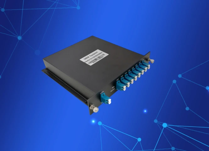
CWDM combines multiple optical signals over one single-mode fiber by assigning each service to a separate wavelength. The wider 20 nm spacing reduces filtering precision and allows the use of lower-cost lasers, optical filters, and passive components. A typical system contains colored transceivers, a cwdm mux demux, patch cables, and one fiber pair or a bidirectional fiber arrangement.
CWDM is commonly used for metro Ethernet, enterprise campuses, mobile backhaul, data center interconnects, surveillance networks, and SaaS infrastructure connecting facilities within a metropolitan area. It is particularly practical when a site needs four to eight wavelengths today and may grow to approximately 12 or 18 wavelengths later. The system remains passive in many deployments, which reduces power consumption and simplifies maintenance.
The broad wavelength range creates an important fiber consideration. Older G.652 fiber may have elevated attenuation near the 1383 nm water-peak region if it is not low-water-peak fiber, also called G.652.D in many modern installations. For CWDM designs using wavelengths around 1371 nm, 1391 nm, or 1411 nm, I verify the fiber attenuation curve before approving the complete channel plan.
A CWDM transmitter converts an electrical service into an optical signal at a defined wavelength, such as 1271 nm, 1291 nm, or 1311 nm. The CWDM mux combines several wavelengths onto one fiber, and the demultiplexer separates them at the receiving site. Each optical path must remain within the transmitter receiver wavelength tolerance and the mux demux insertion-loss specification.
CWDM does not normally require tight frequency stabilization because its 20 nm spacing leaves a relatively wide guard interval between channels. That design reduces component cost, but it also limits spectral efficiency and makes dense channel packing impractical. When I calculate a CWDM link, I focus on total insertion loss, fiber attenuation at each wavelength, connector count, splice count, and the receiver sensitivity required by each optic.
DWDM combines optical signals with much narrower spacing, allowing many more channels to occupy a limited spectral band. Common systems use 100 GHz or 50 GHz channel spacing, while flexible-grid platforms can assign narrower slot widths for selected coherent wavelengths. DWDM is designed for fiber optic backbone networks, telecom transport, cloud connectivity, data center interconnects, and metro or regional networks requiring continued capacity growth.
A DWDM platform may include transponders, mux and demux modules, optical supervisory channels, amplifiers, dispersion management, optical add-drop multiplexers, ROADMs, and network management software. The equipment cost is higher because wavelength accuracy, power control, filtering, and line monitoring requirements are more demanding. The benefit is that a single fiber pair can support dozens of services and can be expanded without installing additional cable.
DWDM commonly operates in the C-band because erbium-doped fiber amplifiers, or EDFAs, can amplify that region efficiently. With suitable transceivers and line systems, operators can carry 10G, 100G, 200G, and 400G services, although the achievable rate depends on modulation, baud rate, forward error correction, fiber quality, dispersion, and optical signal-to-noise ratio.
A DWDM transmitter assigns each service to an ITU-grid wavelength or frequency. The mux combines these channels, amplifiers raise the aggregate optical power, and intermediate sites may add, drop, or pass selected wavelengths. At the destination, the demux separates the channels before the receivers convert them back into electrical data.
For longer links, the design must address more than attenuation. Amplifier spacing, gain flatness, nonlinear effects, chromatic dispersion, polarization effects, optical signal-to-noise ratio, and receiver margin all influence the result. Coherent optics can compensate for several transmission impairments digitally, but they do not remove the need for a complete power and impairment analysis.
Flexible-grid DWDM adds another planning option. Instead of assigning every channel the same fixed 50 GHz slot, the system can allocate spectrum according to the baud rate and modulation format of each service. This can improve spectral utilization, but it requires compatible line cards, ROADMs, control software, and network engineering practices.
There is no single maximum distance for either technology. A practical CWDM span may range from a few kilometers to approximately 40 or 80 kilometers with suitable optics, while some specialized systems reach farther under controlled conditions. DWDM spans may cover tens or hundreds of kilometers with appropriate transceivers, amplifiers, regeneration, and dispersion or impairment management.
The decisive calculation is the optical link budget. I use the following basic model: received power = transmitter power − fiber loss − component loss − engineering margin. Fiber loss is calculated from attenuation per kilometer multiplied by span length, while component loss includes mux demux insertion loss, connectors, splices, patch panels, optical add-drop modules, and amplifier-related penalties.
For example, assume a 40 km link with fiber attenuation of 0.25 dB/km, 4 dB of passive equipment loss, and a 3 dB engineering margin. The estimated loss is 10 dB for fiber, plus 4 dB for equipment, plus 3 dB margin, producing a 17 dB design requirement. If a transceiver pair provides only a 14 dB budget, the link needs lower-loss components, higher-budget optics, regeneration, or a different architecture.
CWDM becomes less attractive when the span requires repeated amplification. CWDM wavelengths cover a broad range, and a single amplifier may not provide uniform gain across every channel without additional filtering or gain equalization. DWDM is generally the better fit for amplified transport because C-band EDFAs and wavelength-control components are widely integrated into DWDM line systems.
CWDM and DWDM applications overlap, but their economic and technical priorities differ. I generally evaluate the number of required wavelengths, service rates, distance, fiber condition, available power, and expected expansion before assigning a technology to a site.
| Network environment | Typical fit | Engineering reason |
|---|---|---|
| Small business or campus network | CWDM | Four to eight wavelengths, short spans, passive equipment, and limited expansion needs |
| Metro Ethernet | CWDM or compact DWDM | CWDM suits moderate capacity; DWDM suits many sites or higher aggregate rates |
| Data center interconnect | CWDM for short links; DWDM for regional links | Choice depends on distance, 100G/400G demand, and fiber availability |
| Mobile backhaul | CWDM or DWDM | CWDM fits moderate fronthaul or backhaul needs; DWDM supports aggregation and growth |
| Telecom regional transport | DWDM | Amplification, optical add-drop, and multiple high-rate channels are common |
| Long-distance fiber backbone | DWDM | Capacity, regeneration planning, coherent optics, and ROADM support favor DWDM |
| Legacy fiber with water-peak concerns | Carefully selected CWDM or DWDM | Wavelength loss must be measured or confirmed from fiber documentation |
For short-distance links, CWDM is often the simpler solution when the required channel count is below 18 and the link budget remains within the selected optics. For long-distance networks, DWDM is usually the more practical architecture because it supports amplification, coherent transmission, and incremental channel activation. Neither choice should be made solely from a vendor channel-count table.
CWDM usually has a lower purchase price because its lasers, filters, mux demux modules, and monitoring requirements are less demanding. DWDM costs more at the beginning because it may require transponders, amplifiers, dispersion analysis, wavelength stabilization, optical monitoring, and specialized management equipment. However, the lower initial price of CWDM does not always produce the lower total cost over the full operating period.
I compare total cost using this model: TCO = optics + mux demux + line equipment + amplification + regeneration + power + installation + maintenance + expansion cost. I then calculate cost per usable channel by dividing TCO by the number of active channels that meet the required link budget and service rate. A system with 8 active channels and a low purchase price may have a higher cost per channel than a DWDM system carrying 40 channels.
| Cost element | CWDM impact | DWDM impact |
|---|---|---|
| Optical modules | Lower cost for moderate rates | Higher cost, especially for coherent optics |
| Mux demux | Passive and comparatively simple | More precise filtering and line-system options |
| Power consumption | Often lower | Higher when amplifiers, transponders, and ROADMs are added |
| Amplification | Limited or specialized | Common in regional and long-haul designs |
| Regeneration | May be needed on extended spans | Planned according to OSNR, dispersion, and service rate |
| Expansion | May require new optics or another fiber pair | Spare channels can be activated progressively |
| Maintenance | Fewer active components | More monitoring and configuration requirements |
As an example, if a CWDM deployment supports 8 usable channels and a DWDM deployment supports 40 usable channels, I do not compare only the rack price. I compare the installed cost per channel, energy cost over the planned service period, expected replacement of optics, and the cost of adding the ninth or tenth wavelength. This approach often changes the preferred solution when growth is expected within three to five years.
A hybrid overlay can be useful when an existing CWDM network has available fiber capacity but a new service requires a different spectral plan. For example, an operator may retain existing CWDM wavelengths for enterprise services and deploy a separate DWDM line system on another fiber pair for high-rate transport. Directly combining CWDM and DWDM on the same fiber requires careful wavelength allocation, filter compatibility, power management, and confirmation that the mux demux equipment supports the combined spectrum.
Another alternative is to use higher-speed point-to-point optics without wavelength multiplexing. This may be appropriate for one or two services over a short span, but it becomes less efficient when multiple services need independent upgrades. A compact DWDM system may also be preferable to repeated CWDM expansions when the fiber route is difficult to replace or lease costs are high.
OPTEKCOM can be included in a supplier comparison when evaluating CWDM transceivers, DWDM optical modules, mux demux equipment, and related fiber transport components. I would compare the proposed bill of materials against the required wavelength grid, insertion loss, optical budget, operating temperature, connector type, monitoring features, and warranty terms rather than selecting equipment by brand name alone.
I use six measurable inputs to choose between the two technologies: span length, channel count, service data rate, fiber type, optical power budget, and growth horizon. The decision should also include the number of intermediate sites, whether optical amplification is required, and whether future services may use coherent 100G, 200G, or 400G optics.
| If your requirement is... | Prefer... | Reason |
|---|---|---|
| Up to 8 active wavelengths and a short metro span | CWDM | Lower equipment complexity and lower initial channel cost |
| Up to 18 wavelengths without amplification | CWDM | The 20 nm grid can provide sufficient capacity |
| More than 18 wavelengths or dense service growth | DWDM | Narrower spacing provides more channels in the same fiber |
| A span requiring EDFA amplification | DWDM | C-band amplification and line monitoring are widely supported |
| 100G, 200G, or 400G coherent transport | DWDM | The platform supports higher spectral efficiency and impairment management |
| A three-year or shorter growth horizon with limited demand | CWDM | Lower upfront investment may match the service forecast |
| A five-year or longer expansion plan | DWDM | Spare channels and modular upgrades can reduce future fiber work |
| Legacy G.652 fiber near the water-peak region | Either, after testing | Wavelength-specific attenuation must be confirmed first |
CWDM is usually the better choice when the network needs a small number of wavelengths, the span is within the transceiver budget, and future growth is predictable. DWDM is usually the better choice when the network needs many channels, amplified sections, long-distance transport, or a clear path to higher-rate optics. If the initial DWDM cost is difficult to justify, I compare it with the cost of installing another fiber pair, replacing CWDM equipment, and performing future migration work.
CWDM vs DWDM: Differences, Applications, and How to Choose comes down to matching the optical architecture with measurable network requirements. CWDM provides a practical solution for short and medium links that need up to 18 broadly spaced wavelengths, moderate service rates, and controlled equipment costs. DWDM supports denser channel plans, optical amplification, coherent transmission, long-distance transport, and expansion beyond the limits of a CWDM grid.
Before purchasing, I document the required channel count, wavelength range, service rate, fiber attenuation, mux demux insertion loss, connector and splice count, transmitter power, receiver sensitivity, and engineering margin. I also calculate cost per usable channel rather than comparing only the initial equipment price. For small business networks, campus links, and moderate metro Ethernet, CWDM is often sufficient; for telecom backbones, regional transport, and data center interconnects with sustained growth, DWDM is usually the more scalable selection.