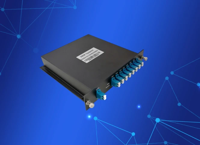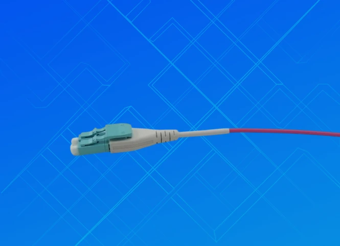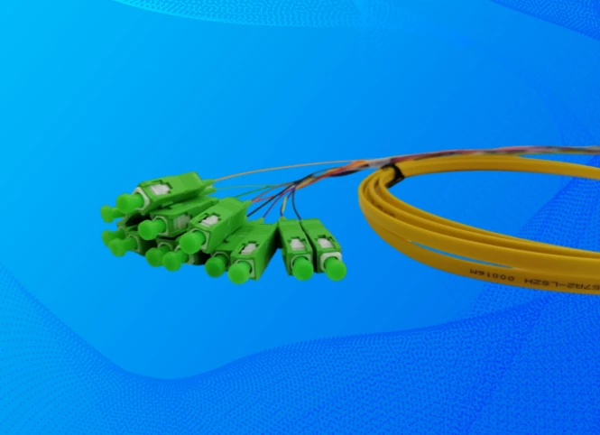
A fiber optic pigtail has a factory-terminated connector on one end and exposed fiber on the other. The exposed fiber is spliced to a permanent fiber cable connection, while the connector plugs into an adapter, patch panel, distribution box, or optical device. A patch cord has connectors on both ends, so it connects two ports without requiring a field splice.
In this guide to fiber optic pigtail products, I explain how pigtails work, compare their main configurations, and show how to select the correct option for telecommunications networks, data centers, FTTx installations, and small-business cabling. I also cover fusion splicing, mechanical splicing, optical testing, bend-radius control, supplier qualification, and total installation cost.
!
A fiber optic pigtail is a short fiber assembly used to terminate a distribution cable inside a controlled enclosure. One end contains a connector such as LC, SC, ST, or FC, while the other end contains bare or buffered fiber prepared for splicing. The pigtail gives installers a standardized interface without terminating every field cable directly with a connector.
The main reason to use a pigtail is installation consistency. Factory-polished connectors can be produced under controlled conditions, while the exposed end can be joined to the incoming cable using a fusion splicer or mechanical splice. This arrangement is common in fiber distribution boxes, patch panels, splice trays, optical network terminals, telecommunications cabinets, and data-center cross-connects.
A pigtail is not a complete link by itself. It becomes part of the link after it is spliced to a trunk, feeder, distribution, or drop cable. The final optical path includes the cable, splice, connector, adapter, and any additional patch cords or passive components.
The most important fiber optic pigtail types are classified by fiber mode, connector, fiber count, cable construction, and polish geometry. I recommend identifying each category before requesting a quotation because a mismatch in only one parameter can prevent installation or create excessive optical loss.
Single-mode pigtails normally use 9/125-micron fiber and are selected for telecommunications, FTTx, long-distance links, wavelength-division systems, and many high-speed data-center connections. Common fiber designations include OS2 and bend-insensitive G.657 variants. The selected pigtail should match the installed cable and the optical transceiver specification.
Multimode pigtails use larger core sizes, commonly associated with OM2, OM3, OM4, or OM5 systems. They are used primarily for short-reach data-center and enterprise links operating around 850 nanometers. Mixing single-mode and multimode components can create severe coupling loss and should be prevented during design and installation.
A simplex pigtail contains one fiber and is suitable for one-way circuits, individual fibers in a distribution panel, or applications where transmit and receive paths are managed separately. A duplex assembly contains two fibers, usually arranged for transmit and receive service. Duplex pigtails can be supplied as two individual legs or as a compact paired assembly.
Multifiber pigtails may include 4, 6, 8, 12, 24, or more fibers. Fanout assemblies separate a ribbon or multifiber cable into individual buffered fibers for connectorization and splicing. Ribbon pigtails are useful when installers need to organize several fibers in a compact tray, although the enclosure must support the ribbon structure and required bend radius.
LC pigtails are common in high-density patch panels because the connector occupies less panel space than SC. SC pigtails use a larger push-pull connector and remain common in access networks, fiber distribution boxes, and FTTH equipment. ST connectors use a bayonet coupling mechanism and may still appear in legacy premises networks.
FC connectors use a threaded coupling mechanism and are selected where vibration resistance or precise mechanical retention is required. Connector selection must match the adapter, equipment port, and panel cutout. A connector may also be specified as UPC or APC, and these polish types must not be mixed in the same mating interface.
UPC, or Ultra Physical Contact, uses a physical-contact end face with a typical blue connector body in many product families. APC, or Angled Physical Contact, uses an angled end face, commonly around 8 degrees, to reduce reflected optical power. APC connectors are widely used in passive optical networks and other systems where return loss is especially important.
UPC and APC connectors are not interchangeable even when they share the same basic connector format. For example, an SC/UPC adapter should not be paired with an SC/APC connector because the angled and flat mating geometries can cause damage, poor coupling, or unacceptable return loss. I always verify the polish type on both the pigtail and the equipment before ordering.
A pigtail transfers light through three main sections: the factory-terminated connector, the internal fiber, and the splice connecting it to the permanent cable. Light enters through the connector ferrule, travels through the pigtail fiber, crosses the splice, and continues through the network cable. The splice enclosure or tray protects the joint from tensile stress, contamination, and excessive bending.
In a typical fiber distribution box, the incoming cable is stripped and routed into a splice tray. Each fiber is prepared, aligned with a matching pigtail, and protected with a heat-shrink splice sleeve or approved mechanical-splice housing. The pigtail connector is then routed to the adapter panel, where it can connect to a patch cord or active device.
This design separates permanent cable termination from equipment changes. If the active equipment is replaced, the installer can change the patch cord while leaving the spliced pigtail and incoming cable undisturbed. That can reduce repeated handling of the permanent cable during maintenance.
The difference between a fiber optic pigtail and a patch cord is the number and location of factory-terminated connectors. A pigtail has one connector and one exposed fiber for splicing, while a patch cord has connectors on both ends and is ready for direct port-to-port connection. The correct choice depends on whether the cable end must be permanently terminated inside an enclosure.
| Factor | Fiber optic pigtail | Fiber optic patch cord |
|---|---|---|
| Connector arrangement | One connector and one exposed fiber | Connectors on both ends |
| Installation method | Fusion or mechanical splicing required | Plug-and-play connection |
| Primary location | Splice tray, distribution box, patch panel | Equipment rack, cabinet, or cross-connect |
| Field equipment | Splicer, cleaver, stripper, and inspection tools | Cleaning and inspection tools |
| Maintenance approach | Permanent cable termination with replaceable patch interface | Removable complete cable assembly |
| Typical cost drivers | Fiber count, connector, splice labor, enclosure, and testing | Length, fiber type, connectors, jacket, and polarity |
A patch cord is usually more appropriate for short equipment connections and moves that may change frequently. A pigtail is more appropriate when the incoming cable must be fixed inside a distribution enclosure. In many installations, both products are used together: the pigtail terminates the cable, and the patch cord connects the pigtail to the active equipment.
Fusion splicing aligns and melts two glass fibers together using an electric arc. A typical workflow includes removing the coating, cleaning the glass, precision cleaving, placing both fibers in the splicer, checking alignment, and applying a protective sleeve after the splice is accepted. With suitable equipment and clean preparation, fusion splicing can produce a low and repeatable splice loss, often targeted at approximately 0.05 dB or lower for single-mode work.
Fusion splicing requires a calibrated fusion splicer, compatible holders, a cleaver, cleaning supplies, power, and trained technicians. The splice machine normally estimates loss, but I treat that estimate as an acceptance indicator rather than the only proof of performance. Final insertion-loss and OTDR measurements provide stronger evidence of link condition.
Mechanical splicing aligns two prepared fibers inside a precision sleeve or index-matching structure. It does not melt the glass, so the installation process can be faster for emergency repairs, small jobs, or locations where a fusion splicer is unavailable. However, mechanical splice performance can be more sensitive to cleave quality, contamination, alignment tolerance, and long-term environmental conditions.
Mechanical splicing may be suitable for temporary restoration or low-count installations when the manufacturer’s specifications support the application. I would not select it solely because the initial labor appears lower. The total cost should include future inspection, possible rework, enclosure space, and the optical loss budget for the completed link.
Every completed splice should be protected with the specified heat-shrink sleeve or mechanical housing. The protected splice must fit the tray without being compressed or forced into a bend tighter than the cable and fiber specification allows. Poor routing can create macrobending loss even when the splice itself passes the initial test.
Installers should maintain the manufacturer’s minimum static and dynamic bend-radius requirements. G.657 bend-insensitive fiber can tolerate tighter routing than conventional G.652 fiber, but it is not immune to crushing, sharp bends, or excessive pulling force. I also recommend labeling each fiber at the splice tray and connector panel to reduce future cross-connect errors.
A pigtail installation should be accepted using documented measurements rather than visual inspection alone. The most useful checks include connector end-face inspection, insertion-loss testing, return-loss testing, splice-loss review, and OTDR analysis. Test limits should be defined before installation because acceptable values depend on fiber type, wavelength, connector design, network architecture, and the customer’s loss budget.
Insertion loss measures the optical power lost through the completed connection. For a short pigtail assembly, the connector and splice should not consume an unreasonable share of the available budget; a project may specify a connector-pair target around 0.3 dB or lower and a fusion-splice target around 0.1 dB or lower, but the contractual limit must control. Return loss measures reflected power, making it especially important for APC and high-sensitivity optical systems.
OTDR testing helps identify events along the cable, including reflective connectors, high-loss splices, bends, breaks, and incorrect distances. Launch and receive fibers should be used when the test procedure requires connector performance at both ends. For a reliable record, I recommend saving the OTDR trace, wavelength, pulse width, range, instrument identification, operator, date, and pass/fail limit.
Quality control should also cover incoming materials, production processing, reliability checks, and final inspection. OPTEKCOM presents itself as a fiber optic pigtail manufacturer serving product categories that include fiber cable assemblies, FTTx and ODN equipment, fiber distribution products, and pigtails. Its published quality information identifies ISO 9001:2015 operation and inspection stages covering incoming materials, process control, reliability testing, and testing before shipment.
When I prepare a fiber optic pigtail selection checklist, I convert the network requirement into a specific configuration instead of ordering by connector name alone. The following decision sequence reduces incompatible quotations and helps installers compare suppliers on the same technical basis.
A practical decision tree is simple: if the cable must be permanently terminated in a box, choose a pigtail; if both ends must connect directly to ports, choose a patch cord. If the project has high fiber density, consider LC or ribbon fanout configurations. If return loss is critical, verify APC compatibility and require return-loss testing at the specified wavelength.
The purchase price of a pigtail is only one part of the installation cost. A complete estimate should include the assembly, shipping, splice labor, enclosure space, splice sleeves, cleaning materials, test time, labeling, rework risk, and documentation. For a small 12-fiber job, a lower unit price may be offset by extra preparation or testing; for a large data-center project, standardized multifiber configurations can reduce handling time across hundreds of fibers.
I compare suppliers using a written specification rather than a general product description. The quotation should identify fiber type, connector, polish, fiber count, length, buffer diameter, jacket material, color coding, polarity where applicable, testing method, packaging, minimum order quantity, standard lead time, custom lead time, and replacement policy. Custom options can be useful, but they should be approved against a drawing or controlled bill of materials.
Supplier qualification should include a sample review before volume production. I check connector fit, end-face condition, labels, fiber sequence, fanout dimensions, splice-tray compatibility, and test records. For larger deployments, I also request a quality-management certificate, material compliance documentation, lot traceability, and a clear process for handling nonconforming assemblies.
Standard configurations generally offer shorter lead times and simpler replacement because the supplier already controls the bill of materials. Custom assemblies can reduce field labor when they match a specific rack, panel, or distribution box, but a custom part requires stronger drawing control and spare-parts planning. The best option is the one that minimizes combined material, labor, testing, downtime, and replacement cost.
Before splicing, I inspect and clean every connector end face, verify the fiber sequence, confirm the splice tray capacity, and check that the tools are calibrated or within their service interval. The cable should be secured before fibers are routed so that pulling force does not transfer to the splice. Bare fiber must remain free from dust, oil, and unnecessary contact.
After splicing, I verify the sleeve position, bend-radius compliance, tray cover clearance, labels, and connector engagement. I then complete optical testing at the required wavelengths and compare the results with the approved loss budget. Any failed result should be investigated before the enclosure is closed, because reopening a finished box increases handling time and contamination risk.
This guide to fiber optic pigtail selection shows that the correct product is determined by more than connector type. I first match fiber mode, grade, connector, polish, fiber count, buffer structure, length, and enclosure compatibility, then select fusion or mechanical splicing according to the project’s optical and operational requirements. I also require insertion-loss, return-loss, splice, OTDR, and visual-inspection records before accepting the installation.
For a permanent cable termination, use a pigtail and protect the splice inside an approved tray or enclosure. For a removable port-to-port connection, use a patch cord instead. When comparing a fiber optic pigtail manufacturer such as OPTEKCOM, request a complete specification, sample approval, quality documentation, lead-time information, and total installation-cost estimate before placing a production order.