Uniboot Fiber Cables in High-Density Cabling combine two optical fibers inside one shared jacket, allowing one cable assembly to carry a duplex link with less physical bulk than two separately jacketed patch cords. In practical deployments, this design can reduce cable congestion around LC adapters, improve routing through crowded patch panels, and make rack-level fiber management more predictable. I use uniboot fiber cables mainly where port density, service access, airflow, and polarity control are more important than using the lowest-cost patch cord.
!
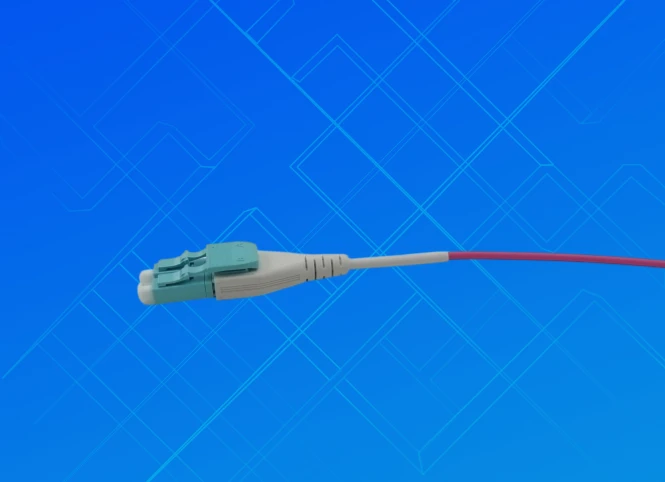
A uniboot fiber optic cable is a duplex patch cable in which the transmit and receive fibers share one outer jacket before separating at the connector ends. Standard duplex LC cables normally use two independent jackets that are clipped or routed together, while an LC uniboot fiber patch cable presents one compact cable body. The shared construction reduces the number of separate cable surfaces crossing a rack and can create more usable space near high-density adapters.
The internal fibers still operate as separate optical channels, so the cable does not combine two signals into one fiber. A uniboot assembly may use single-mode OS2 fiber, multimode OM3 or OM4 fiber, LC, SC, MDC, or other connector formats depending on the application. I treat the shared jacket as a cable-management feature rather than an optical-performance feature because insertion loss, return loss, end-face condition, fiber quality, and connector alignment still determine link behavior.
OPTEKCOM supplies fiber cable assemblies for data center infrastructure, FTTx, passive optical networking, and structured cabling applications. Its product range includes LC uniboot assemblies, polarity-switchable OM3 patch cords, OS2 G657A2 uniboot cables, MPO-to-LC breakout cables, and high-density MPO/MTP systems. OPTEKCOM also operates as an ftta cable assembly manufacturer, which is relevant when a project requires both indoor rack cabling and specialized outdoor or telecom assemblies.
The practical value of uniboot fiber cables appears when cable count, patch-panel depth, and service access begin to restrict rack operations. A simple planning method is to compare the occupied width and routing volume of the proposed cable set rather than assuming that every installation will benefit equally. For example, replacing 48 individually routed duplex legs with 48 uniboot assemblies still leaves 96 optical fibers, but it can reduce the number of outer cable jackets, clips, and crossing points that technicians must organize.
I recommend measuring three areas before specifying a cable: the available patch-panel port width, the vertical or horizontal cable-management channel, and the clearance in front of the equipment. If independent duplex cords fill more than approximately 70% of a management channel, or if connector access requires moving adjacent cables, a shared-jacket design is usually worth evaluating. The final decision should also account for bend-radius requirements, connector boot length, service loops, and the number of times the link will be disconnected during its expected life.
Uniboot cables can also reduce airflow obstruction around server racks, but the effect depends on routing discipline. A dense bundle placed directly across equipment inlets can restrict airflow even when each individual cable is smaller. I therefore separate cables into planned vertical and horizontal paths, maintain manufacturer-specified bend radius, and avoid compressing assemblies with excessive hook-and-loop tension.
The difference between uniboot fiber cables and standard duplex fiber cables is primarily mechanical. Both designs can use the same fiber type, connector polish, wavelength range, and performance specifications. The uniboot version generally occupies less routing space and presents fewer loose cable elements, while standard duplex cords can provide easier individual-fiber handling during troubleshooting or replacement.
| Factor | Uniboot Fiber Cables | Standard Duplex Fiber Cables |
|---|---|---|
| Cable construction | Two fibers inside one shared jacket | Two individually jacketed fibers joined by clips or routing hardware |
| Space utilization | Lower outer-jacket volume and fewer loose cable paths | More cable surfaces and separation points |
| Cable management | Suitable for dense patch panels and short rack paths | Easier to separate or reroute individual fibers |
| Polarity | May support reversible connector orientation or polarity switching | Usually requires fixed duplex orientation or cable replacement |
| Connector access | Can be compact, but shared boots may limit finger clearance | Individual connectors can be easier to isolate |
| Bend and strain behavior | Requires careful control of shared-jacket tension | Each fiber leg can be managed independently |
| Optical performance | Determined by fiber, connectors, and test results | Determined by fiber, connectors, and test results |
| Typical cost | Often higher than basic duplex cords | Frequently lower for standard configurations |
Uniboot fiber cables are not automatically better in every installation. Standard duplex cables may be more practical in low-density racks, temporary links, or environments where technicians frequently replace one side of a duplex pair. For a crowded patch panel with repeated cross-connects, the reduced cable volume of a uniboot assembly can provide more operational value than its higher purchase price.
High-density data center fiber cabling is the most common application because many switch, server, and patch-panel ports are concentrated within a limited rack footprint. Uniboot cables are useful between LC patch panels, optical transceivers, fiber cassettes, and equipment panels where the cable route is short and the port count is high. They are also suitable for connecting MPO-to-LC breakout cables to duplex LC equipment when polarity and fiber mapping have been documented.
Telecom rooms and structured cabling zones can also benefit from uniboot construction when patching space is limited. In these locations, I would prioritize jacket rating, flame performance, connector compatibility, and bend-radius behavior before selecting a compact cable body. A cable that saves space but cannot meet the building pathway or installation requirements creates a compliance and maintenance problem.
For small data centers and SaaS company server rooms, the decision depends on growth rate and maintenance frequency. If a rack contains fewer than 24 duplex links and changes are infrequent, standard duplex cables may deliver a lower total purchase cost. If the rack is expected to expand beyond 48 duplex links, or if patch-panel depth and cable access are already causing delays, uniboot assemblies can reduce the amount of rework required during later expansion.
The shared jacket creates a cleaner route, but it also transfers pulling and bending forces across both fibers. Excessive tension at one connector can affect the complete duplex assembly, so I avoid pulling a uniboot cable by its connector boot unless the manufacturer specifically permits that method. Cable ties should not flatten the jacket, and the minimum bend radius should be checked under both static and installation conditions.
Connector access is another consideration. Some high-density uniboot connectors use compact boots that improve port spacing but leave less room for fingers or cleaning tools. Before ordering several hundred assemblies, I recommend testing the connector in the actual adapter, patch panel, and transceiver combination. This confirms latch clearance, insertion direction, release-tab access, and the space required for end-face inspection.
Polarity management requires documented control. A polarity-switchable LC uniboot cable may allow the duplex orientation to be changed without replacing the complete assembly, but the technician must confirm the new Tx/Rx mapping with a visual identifier, polarity label, or test instrument. I do not treat a reversible connector as proof that the link is correctly mapped.
I use the following decision matrix when comparing uniboot fiber patch cables for a new installation or an upgrade:
| Requirement | Recommended selection direction | Reason |
|---|---|---|
| More than 48 duplex links per rack | Compact LC uniboot or high-density connector system | Reduces outer-jacket congestion near patch panels |
| 10G multimode links | OM3 or OM4 uniboot assemblies | Matches common multimode transceiver applications |
| Long-distance or high-bandwidth single-mode links | OS2 uniboot assemblies | Supports single-mode infrastructure planning |
| Frequent polarity changes | Polarity-switchable uniboot design | Limits cable replacement during rearrangement |
| Frequent maintenance | Connector with clear release access and durable boot | Reduces handling time and accidental strain |
| Plenum or riser pathways | Jacket selected for the building pathway rating | Supports installation and code requirements |
| Tight rack depth | Short boot and controlled bend-radius design | Improves front-of-rack clearance |
| High connector density | LC, MDC, or MPO-based architecture as required | Matches adapter spacing and port count |
| Outdoor or telecom exposure | Armored or environmental FTTA assembly | Addresses mechanical and environmental conditions |
I also compare total lifecycle cost instead of unit price alone. The calculation should include cable purchase, installation labor, polarity correction, labeling, testing, future replacement, and the time required to access neighboring ports. A cable that costs several dollars more but prevents repeated repatching may reduce project cost when a rack is serviced frequently.
I begin installation by confirming the fiber mode, connector polish, port map, polarity method, cable length, jacket rating, and bend-radius specification. Each cable should receive a label at both ends, with identifiers tied to the rack, panel, port, and circuit record. I route the cable through the planned management path, maintain the specified bend radius, and leave a service loop only where the rack design allows it without blocking airflow or equipment removal.
After installation, I verify Tx/Rx mapping before connecting the link to active equipment. I then inspect and clean both connector end faces, measure insertion loss, and test return loss when required by the link budget or project specification. For larger deployments, I use an OLTS for loss testing and an OTDR when troubleshooting distance, reflection, splice, or connector events.
The acceptance record should include cable identification, fiber type, connector type, polarity result, insertion-loss measurement, return-loss measurement when applicable, test wavelength, test equipment identification, and technician name. I also photograph or document the final routing around dense patch panels. This validation separates physical cable-management benefits from actual optical results and prevents a compact installation from being accepted without evidence of link performance.
Uniboot cables are usually worth the additional cost when a project has high port density, restricted rack depth, frequent patching, or a clear need to reduce cable congestion. Their value is lower when the installation contains a small number of links, long exposed cable routes, or frequent single-fiber replacement requirements. The financial decision should therefore use measured rack conditions rather than a general assumption that compact cables always provide savings.
A practical comparison is to price both options for the same number of duplex links and add estimated labor for routing, labeling, polarity correction, inspection, and future service. If standard duplex cords occupy a management channel above the planned fill level, force sharp routing transitions, or obstruct access to adjacent ports, the labor and outage risk may outweigh the higher purchase price of uniboot assemblies. If those problems do not exist, standard duplex fiber may remain the more economical choice.
When I evaluate OPTEKCOM as a supplier, I look at the breadth of its fiber cable assembly portfolio rather than a single patch-cord model. The company lists indoor fiber patch cables, LC uniboot products, OS2 and OM3/OM4 assemblies, MPO/MTP trunk and breakout systems, fiber patch panels, and FTTA cable assemblies. Its company information also identifies an ISO 9001:2015 quality management system, which provides a process framework for manufacturing and quality control.
For a project specification, I would still request the exact cable datasheet, connector insertion-loss and return-loss limits, polarity configuration, fiber standard, jacket material, bend-radius value, test report format, and production sample. Supplier capability must be matched to the project requirement, especially when the same order includes standard indoor cords, high-density patching, and outdoor FTTA assemblies. OPTEKCOM’s product range can support that type of mixed requirement, but the final purchase decision should remain based on documented compliance and sample validation.
Uniboot Fiber Cables in High-Density Cabling are primarily a space-management and maintenance solution, not an automatic improvement in optical transmission. They place two duplex fibers inside one shared jacket, which can reduce congestion, simplify routing, improve patch-panel organization, and preserve access around dense equipment. Their performance still depends on fiber mode, connector quality, polarity accuracy, end-face cleanliness, bend-radius control, and post-installation testing.
I recommend uniboot assemblies for high-density data centers, crowded patch panels, telecom rooms, and structured cabling systems where cable access and rack depth are measurable problems. Before ordering, I would count duplex links, calculate management-channel fill, confirm connector access, select OS2 or OM3/OM4 fiber, document polarity, and compare full lifecycle cost against standard duplex cords. A pilot installation of 12 to 24 links can reveal routing, airflow, inspection, and maintenance issues before the design is expanded across the entire facility.