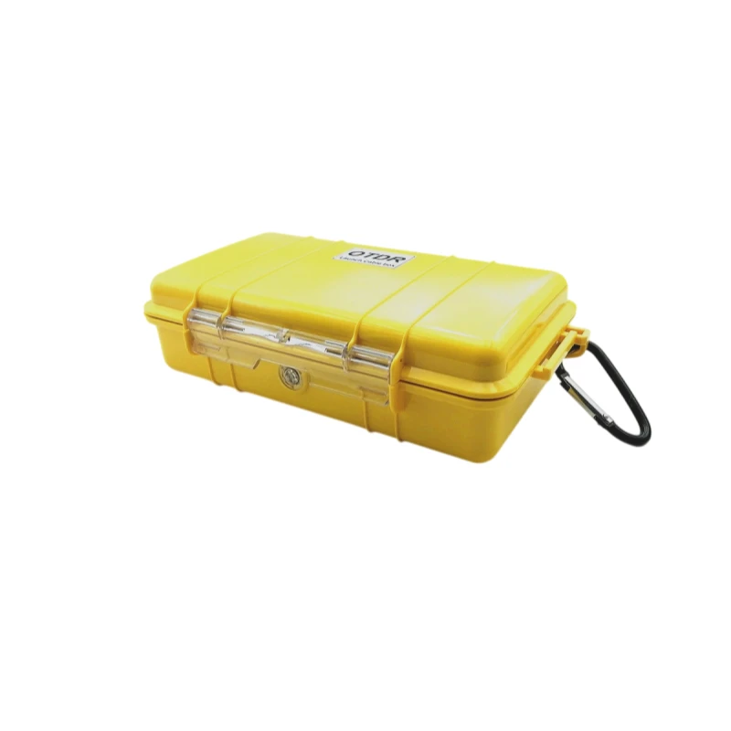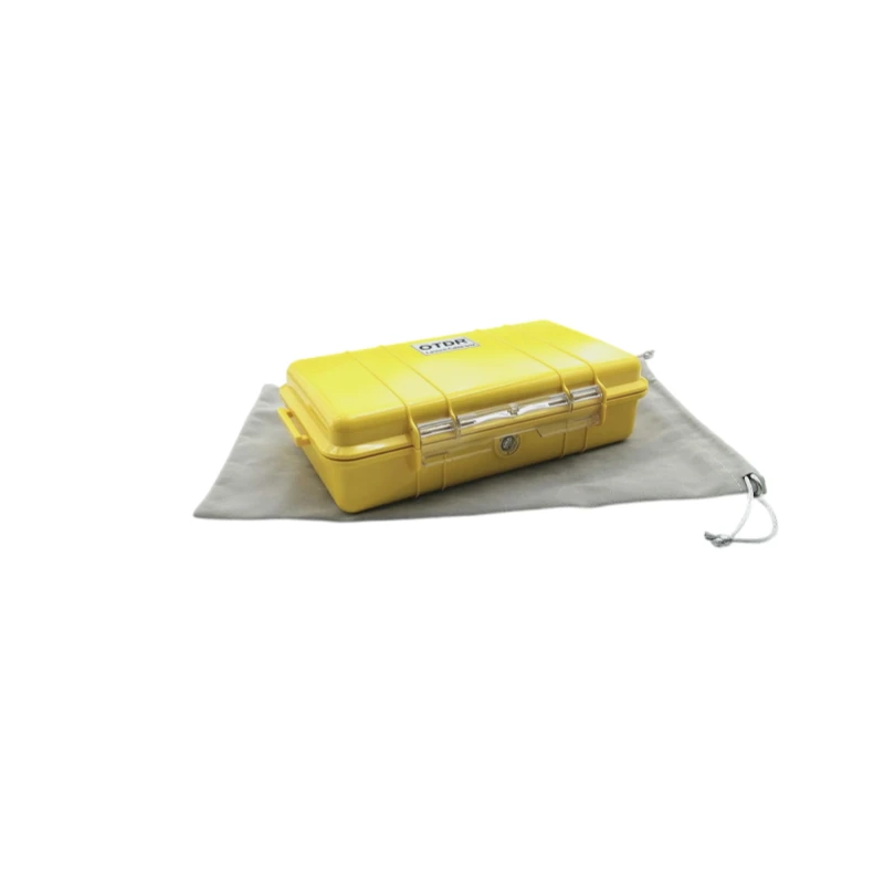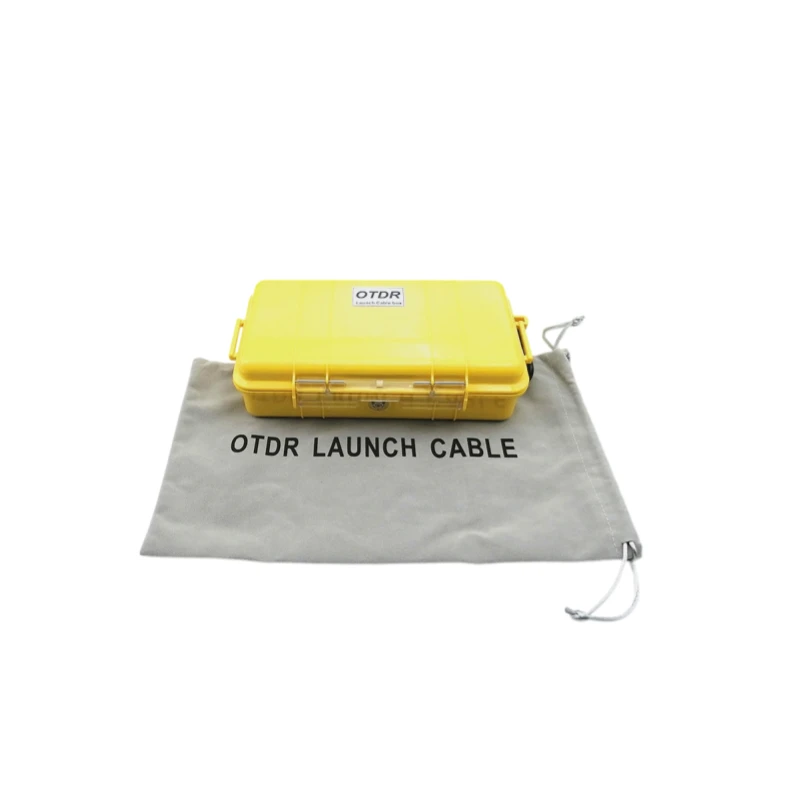
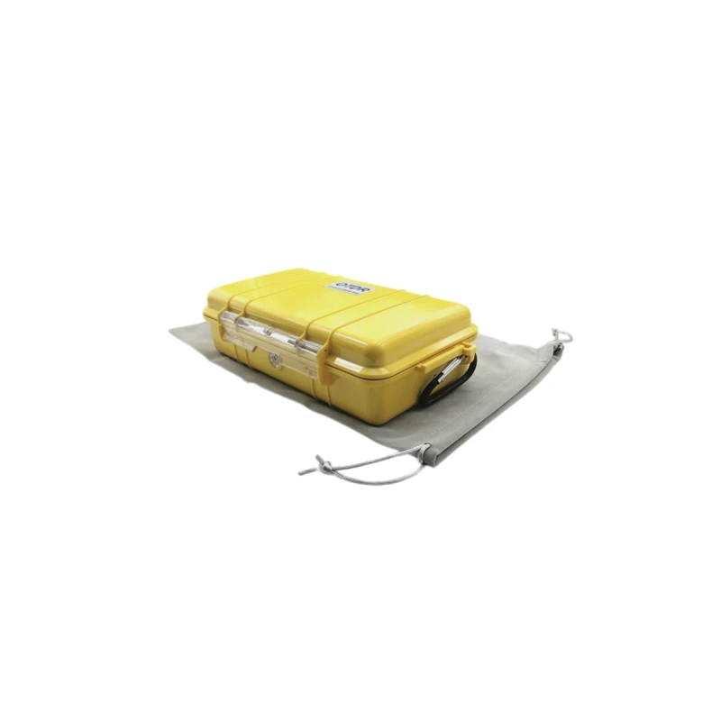


An OTDR launch cable, which connects the OTDR to the link-under-test, discloses the insertion loss and reflectance of the near-end connection. It is used to create the proper conditions for testing another similar optical fiber for faults. This method avoids undesirable variations in loss and distance measurements. A launch fiber will help to overcome the blind spot or Dead Zone of an OTDR brought about by high launch power or faults near the launch end of the fiber.
Compact and rugged packaging.
Portable for field use.
Prevents fiber damage and ensures accurate results.
Fiber Network Installation and Acceptance
Fiber Maintenance and Fault Localization
Fiber Network Optimization
Fiber Characteristic Analysi
| Items | Parameters |
|---|---|
| Fiber Type | G652D, G657A, OM1, OM2, OM3, OM4 |
| Fiber Length | 500m/ 1Km/ 2km |
| Case Dimension | 23.8CMx 14.1CM x 6.7CM |
| Case Material | SR Polypropylene |
| Case Color | Yellow |
| Operating temperature | -40 ° to + 55 °C |
| Return loss | UPC ≥ 50dB, APC ≥ 60dB |
| Weight | 0.75 kg (without fiber) |